Blogg
Här finns tekniska artiklar, presentationer och nyheter om arkitektur och systemutveckling. Håll dig uppdaterad, följ oss på LinkedIn
Här finns tekniska artiklar, presentationer och nyheter om arkitektur och systemutveckling. Håll dig uppdaterad, följ oss på LinkedIn

In the world of information architecture, UML still has a strong foothold. Therefore class diagrams are still desired, even when designing RESTful APIs. I have therefore sought a way to represent the pieces that make up an API as UML and found that although this is somewhat intuitive, there is not one set way of doing this. This post describes our way of using UML to create a hybrid web service model/information model.
For our project we on the one hand had a need for a web service model capturing resources and sub-resources and the relations or paths between them, and on the other hand we needed a information model to aid in designing the web services and underlying database by capturing the datamodel and the attributes, datatypes and subcomponents that made up each resource or sub-resource. For this we extended the UML-notatin so that we were able to capture all of this in one class diagram.
Inspired by the guide to designing RESTful web services provided by IBM, using ratonal rose (although we we used a different modeling tool) we started of with making a basic web service model of the solution.
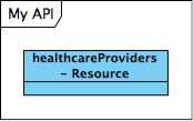
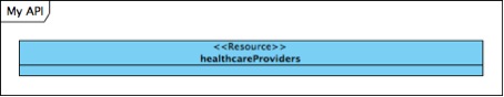
Step one was to make classes identifiable as resources. This was done by writing “Resource” after the class name:
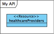
Perhaps a better way to do this would have been to create a stereotype called Resource, because then you get the nice <<…>>. So here we go:
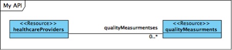
Then we needed to capture the relation between two or more resources. To do this we used a simple association, and gave it a name in the direction which indicated the path used to reach it:
Again, perhaps a steteotype would have been expected, and then using a one way arrow helps to show the direction of the relation. The way to do this would be like this:
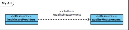
But here we felt we lost something by leaving out the cardinality of the relation. This might be of little interest for a consumer of the API, but it helps the developer of the underlying database to make the right assumptions about the composition of classes.
We initially played around with the idea of making some relations go in both directions making both resources each others sub-resources. In the final design instead modeled our api like a database having a relation from class A to B and adding the unique identifier of A to B, much like a foreign key. More about this in the section “Addressing the information model needs”.
As we relied on a convention of making all resources available as both top level resources of their own even if they primarily served as sub-resources we skipped linking them to a top level application. We later introduced this in a separate web service model for clarity, but during the development phase it served no need.
We would have ended up with a lot of lines if all classes had to connect to a top level class representing the application like this:
As we relied on the convention of naming all resources in plural names the relations between resources and sub-resources were given plural names.
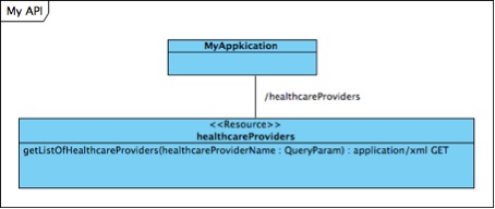
Also we used the convention of retrieving a list of all objects by the url myApplication/healthcareProviders/ and retrieving one object by it’s identity myApplication/healthcareProviders/{healthcareProviderId}/.
This allowed us to skip having one class representing the whole collection and one class representing one entity. This is great for when you finish up ypur project and want to document the final web service model:
But during the development phase of our project we kept it simple like this:
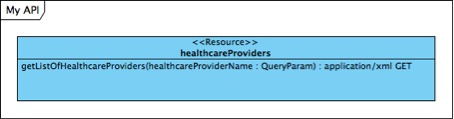
As all resources were “read only” and only supported GET we simply left out specifying the method. Also we relied on the convention to make all attributes in the response searchable we also didn’t have to specify specific query-attributes per resource:
It doesn’t hurt to add methods, but they make things less agile as things might move around in the model. Here the methods are included:
Here is where we step away from the traditional UML representation of an API by exposing the attributes that make up each resource in the same model. The “proper” place for this would be as output from the get-method of each resource, but this made datatype, identifyers, cardinality and sub-components invisible in the model, so why not incorporate some of the conventions of representing xml-schemas in UML into the diagram to capture more in a single view?
In this example the output of a get method of one healthcareProvider returns a healthcareProviderId, we can then specify that it’s an int and we let the “unique” flag convey that it’s the identifier of this resource:
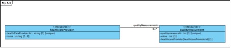
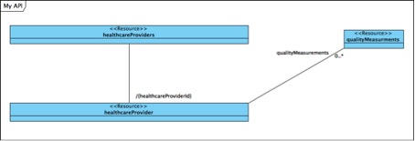
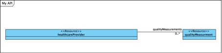
The foreign key convention governing this design leads us to myApplication/healthcareProviders/ having a sub-resource reached through myapplication/healthcareProviders/{healthcareProviderId}/qualityMeasurments/
The sub-resource qualityMeasurments then has an attribute named like the resource and with a modifier showing it is the healthcareProviderId that is returned. In the final xml this is just a simple
<healthcareProvider>{healthcareProviderId}</healthcareProvider>.
The output of a resource isn’t just a straight list of attributed, so we needed to find a way to represent more complex structures. We had the example of needing to embed the author in the output instead of making it a resource of it’s own. For this we used compositon-associations in a manner similar to that used when modeling XML-schemas in UML:
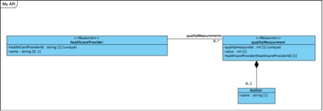
Using this approach made it really easy to get an overview of the entire domain in one view. This enabled us to make changes in the design and still ensuring that - Attributes were not forgotten when merging or splitting resources - Naming conventions of attibutes were followed. - All relations were working in the directions intended
It also made it easy to alter between having something embedded in the output and having it a resource of it’s own, we simply just changed the relation.
Though primarily serving as a model for aiding in the design of the underlying datamodel and for developing the web services, this model also made it quite easy to create the required documentation for the domain. - It made it easy to construct a web service model as all the information was already captured in this model. - It made it easy to specify the output of each resource as we just did a cut and paste of the resource together with it’s compositions.
However some things were not addressed as it was out of scope for our domain, such as aliases for quick searches, redirects and having to incorporate external systems into our design.